Forced Air Flotation Cell
Working Principle
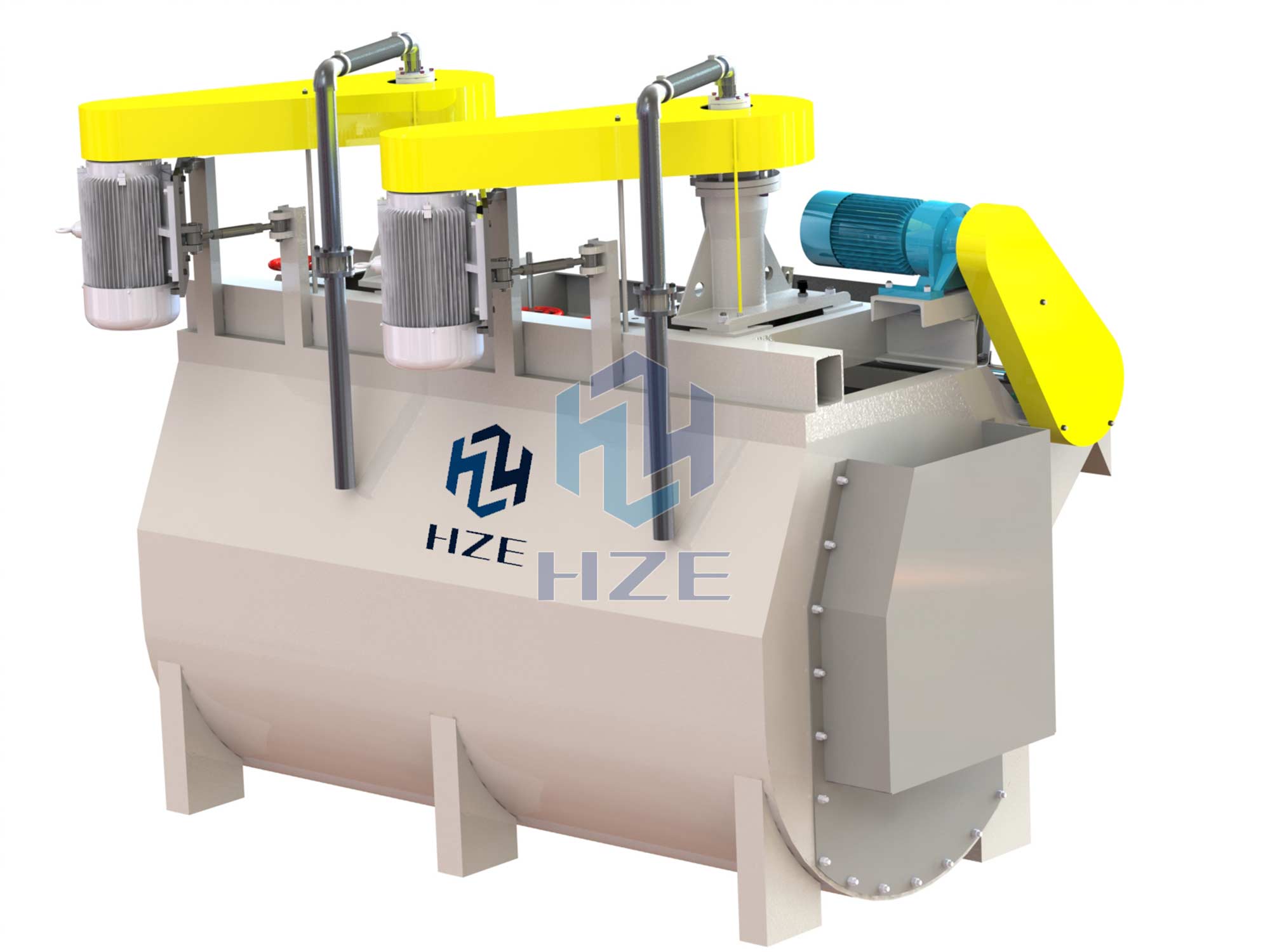
Flotation machine is named as flotation cell and froth flotation concentrator.
When flotation cell is at work, ore slurry all around going through cell bottom is sucked into the interval between impeller and vane from the lower end of the impeller with the rotation of the impeller. Meanwhile, the low-pressure air produced by the blower going into it will go through air distributor in trunnion and impeller chamber. After the full mixture of ore slurry and air in the interval between vanes, they are pushed from all round of upper half part to above and get into whole cell after steady flow and orientation by the stator.
Air bubbles rise to the froth stability area and the froth overflows from overflow weir into froth tank after concentration process. Another portion of ore slurry flows toward the lower part and forms mineralization bubbles again after agitation of impeller, and the rest of ore slurry will flow to the next tank to become tailings eventually.
Features
The structure and property if XCF cells and KYF cells are similar. The difference is that a stator is specially set above the impeller to form a special negative pressure area for automatic suction of ore slurry, but power consumption will be slightly higher.
XCF and KYF cells can be combined together to be as a complete flotation line.
Application
Flotation cell is one of the most commonly used mining equipment, which is widely used in mineral processing and chemical industries. In the production of small scale, medium scale or large scale mineral processing Plants, it is generally used as the concentration machine for metal ores of gold, silver, copper, lead, zinc, nickel, manganese, iron, molybdenum, tungsten and others, as well as barite, quartz, graphite, feldspar, fluorspar, etc.
Technical Parameters
|
Model |
Effective Volume (m3) |
Capacity (m3/min) |
Impeller Diameter (mm) |
Impeller Speed (r.p.m) |
Inflation Pressure (KPa) |
Air Inflation Flow (m3/m2.min) |
Agitator Power (kW) |
Scraper Power (kW) |
Weight (kg) |
|
XCF-1 |
1 |
0.2-1 |
400 |
358 |
≥12.6 |
≤2 |
5.5 |
1.1 |
1200 |
|
XCF-2 |
2 |
0.4-2 |
470 |
305 |
≥14.7 |
7.5 |
1710 |
||
|
XCF-3 |
3 |
0.6-3 |
540 |
266 |
≥19.8 |
11 |
1.5 |
2300 |
|
|
XCF-4 |
4 |
1.2-4 |
620 |
225 |
≥19.8 |
15 |
2720 |
||
|
XCF-8 |
8 |
3.0-8 |
720 |
175 |
≥21.6 |
22 |
4050 |
||
|
XCF-10 |
10 |
4-10 |
720 |
192 |
≥21.6 |
30 |
4890 |
||
|
XCF-16 |
16 |
4-16 |
860 |
160 |
≥25.5 |
37 |
6600 |
||
|
XCF-24 |
24 |
4-24 |
945 |
166 |
≥30.4 |
55 |
8088 |
||
|
XCF-30 |
30 |
8-30 |
1020 |
138 |
≥31 |
55 |
13550 |
||
|
XCF-38 |
38 |
10-38 |
1050 |
141 |
≥32 |
75 |
14979 |
||
|
XCF-40 |
40 |
10-40 |
1050 |
141 |
≥32 |
75 |
17834 |
||
|
XCF-50 |
50 |
10-40 |
1200 |
125 |
≥35 |
90 |
21878 |
|
Model |
Effective Volume (m3) |
Capacity (m3/min) |
Impeller Diameter (mm) |
Impeller Speed (r.p.m) |
Inflation Pressure (KPa) |
Air Inflation Flow (m3/m2.min) |
Agitator Power (kW) |
Scraper Power (kW) |
Weight (kg) |
|
KYF-1 |
1 |
0.2-1 |
340 |
281 |
≥12.6 |
≤2 |
4 |
1.1 |
980 |
|
KYF-2 |
2 |
0.4-2 |
410 |
247 |
≥14.7 |
5.5 |
2010 |
||
|
KYF-3 |
3 |
0.6-3 |
480 |
219 |
≥19.8 |
7.5 |
1.5 |
1960 |
|
|
KYF-4 |
4 |
1.2-4 |
550 |
200 |
≥19.8 |
11 |
2010 |
||
|
KYF-8 |
8 |
3.0-8 |
630 |
175 |
≥21.6 |
15 |
4060 |
||
|
KYF-10 |
10 |
4-10 |
630 |
192 |
≥2106 |
22 |
4520 |
||
|
KYF-16 |
16 |
4.0-16 |
740 |
160 |
≥25.5 |
30 |
5505 |
||
|
KYF-24 |
24 |
4.0-24 |
800 |
166 |
≥30.4 |
37 |
7600 |
||
|
KYF-30 |
30 |
8-30 |
880 |
135 |
≥31 |
45 |
13140 |
||
|
KYF-38 |
38 |
10-38 |
880 |
138 |
≥32 |
55 |
14621 |
||
|
KYF-40 |
40 |
10-40 |
950 |
135 |
≥32 |
55 |
17569 |
||
|
KYF-50 |
50 |
10-40 |
1030 |
128 |
≥35 |
75 |
21592 |
 DOWNLOAD


